Project CADILLAC: AEW And the US Navy (Part Two)
Project CADILLAC (Part II)
As we celebrate the E-2 Hawkeye’s 50th anniversary, we continue here with Part Two of the Project CADILLAC series.
Project CADILLAC was more than just a program to develop radar; it would develop an entire AEW system — Radar, IFF, relay equipment, shipboard receivers, and airborne platform. Such an undertaking would be ambitious enough in peacetime, at the height of a critical stage in the war it bordered on a divine miracle. – SJS
February 1944. In Europe the invasion of Italy is well underway and the Battle of Monte Casino is engaged. Eisenhower establishes SHAFE headquarters in Britain. The RAF drops 2300 tons on Berlin, the 8th AF begins the “Big Week” bombing campaign and Soviet troops continue the offensive begin at Novgorod and Leningrad. In the Pacific US forces have landed and captured the Marshall Islands and have moved on to Eniwetok Atoll. In the south, MacArthur’s forces have begun Operation Brewer in the Admiralty Islands. The tide, ever so imperceptibly, is turning in favor of the Allies. In Japan, Commander Asaiki Tamai asked a group of 23 talented student pilots, whom he had personally trained, to volunteer for a special attack force. All of the pilots raised both of their hands, thereby volunteering to join the operation.
In the US, the fruits of scientific research and technological prowess were starting to manifest €“ high altitude bombers, Essex-class carriers, jet engines; the beginnings of nuclear weapons. At the MIT-RL, proposals were being developed for an ambitious program to create an AEW system for deployment with the fast carrier forces in the Pacific Fleet. The hope was for the system to be operational in time for Operation DOWNFALL, the projected invasion of the Japanese homeland, slated for sometime in early 1946. Following a series of meetings with reps from the Navy’s Bureau of Ordnance (BuOrd) the Navy formally requested the National Defense Research Committee (NDRC) to establish the project. Ultimately, the project would include 9 of MIT-RL’s 11 laboratories, BuAer, BuShips, Naval Air Modification Center, Philadelphia, Naval Research Lab, several Navy contractors and Radiation Lab subcontractors and over 160 officers and men. The project was eventually given the code name of “CADILLAC,” the name of the highest mountain on the eastern seaboard and in the fall and winter, the location of the first sunrise in the lower 48 states. It would serve as the site of some of the developmental relay work because of its height and proximity to the sea.
As originally envisioned, CADILLAC would consist of two elements (see: CONOPS Illustration): one airborne (“AEW Aircraft”) and the other shipboard (“CV CIC”). The airborne unit would carry the APS-20 radar, IFF and VHF comms and relay equipment, acting as an airborne radar and relay platform for the ship. Back on the ship, the radar picture from the airborne unit would be relayed via a VHF video data link and displayed on a dedicated PPI (Plan Position Indicator) scope. Communications with far-flung fighter CAP would also be relayed through the airborne unit. Sorting out friend from foe would be via the newly developed IFF or Identification Friend Foe system which relied on an aircraft responding to electronic €œchallenge€ signals with a coded pulse train. The airborne unit would also have the ability to display ownship’s radar picture and have a limited ability to control fighters, but this was planned to be a fall-back capability.

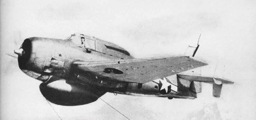
Aircraft. The aircraft chosen was the only carrier-based aircraft large enough to accommodate the 8-foot radome and 2,300 lbs of associated equipment. Stripped of turret, armor, and armament, a TBM-3 Avenger served as the initial platform for CADILLAC. Besides the CADILLAC equipment, the XTBM-3W was modified to include an engine driven high power generator, additional tail stabilizers, addition of a crewman position in the aft fuselage and over 9 separate antennas on the fuselage, tail, and wings.

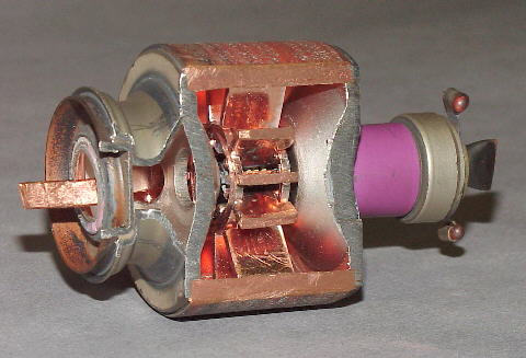
Airborne System. The AN/APS-20, developed as part of the CADILLAC program, was a 10cm set that had a peak power output of 1 megawatt and a 2-second pulse. The design of the APS-20 radar was so sound that variations of this same radar would see use well into the 1960s on a variety of USN, USAF and allied AEW platforms, until it was ultimately replaced by the E-2’s APS-96/120 series among others. The IFF system was built around the AN/APX-13 with a very high power (2 kW) transmitter and one of the most sensitive receivers in this type application. It was designed to enable ID of targets on both the (then) Navy standard A and G bands at ranges comparable to the radar. To “pipe” this information back to the ship, the AN/ART-22 relay-radar transmitter, broadcast the picture back to the ship on a 300 mc frequency.The radar synchronizer also synchronized the IFF and relay signals, encoding their outputs to ensure reception even in an environment characterized by heavy enemy jamming and intrusion. Remote operation of the airborne system from the ship was made possible by the AN/ARW-35 receiver, AN/ARC-18 shipboard relay and the use of a modified flux gate valve to stabilize and orient the radar display to true North (ed. note: not altogether different from the system that was used in the E-2 almost 2 decades later). All this, of course, was in addition to the usual complement of voice comm., IFF, and flight/navigation gear. Space, as one can see from the cutaway, was at a premium, even in the large-bodied Avenger.
Shipboard System. The shipboard system primarily consisted of relay (which included omnidirectional or a horizontal diversity receiver), decoding, and shipboard signal distribution equipment. The signal was passed to 2-3 PPI scopes, located in CIC. In CIC, the picture was merged with that of the ship in a manner that eliminated motion induced by the AEW platform – in other words, a ground-stabilized picture oriented to true north. That picture could be expanded to a 20nm view for detailed examination of sectors of interest. When tied together with voice communications, the implications of this capability were astounding.
Let us step back for a moment and review what the CONOP and ‘to be’ CADILLAC system would provide. Expanded radar coverage, in theory out to 200 nm. Positive identification of friendly aircraft in that volume of surveyed airspace. The ability to effect positive control of interceptors much closer to expected enemy marshaling points. Detect and track friendly and hostile surface units (including snorkeling submarines). Finally, the ability to bring all this information together and display it in CIC enabling informed decision-making from unit up to Fleet level.
We who have been fortunate enough to have operated in the age of modern AEW aircraft, digital data links and automated detection and display systems take these for granted. It is not until one or more elements are removed that their intrinsic value is appreciated. This was something the Royal Navy painfully re-discovered during the war to reclaim the Falklands/Malvinas. That the concept, much less the hardware and integration of these many disparate elements was conceived and executed in a wartime situation says much about the technical verve and capabilities of this band of naval and civilian scientists, engineers and operators. The process of how this was brought to reality and IOC will be the subject of the next installment.
To Be Continued


